I thought that this month I would take the opportunity to go back to basics and give a brief insight into how Groundforce propriety equipment operates and to try and explain what is actually going on within the struts when you get to work on the hand pump, or when you simply flick the lever on the labour saving motorised pump.
The best way to explain this is to firstly show you a 3D representation of what it looks like on the inside of one of our high capacity double acting struts.
Most of our hydraulic rams have 1.0m of stroke (hydraulic adjustment). As shown above, the ram itself is housed within the inner sleeve section of the strut casing whilst the piston rod is connected to the outer sleeve which is free to slide along the innersleeve as the ram is pumped in or out.
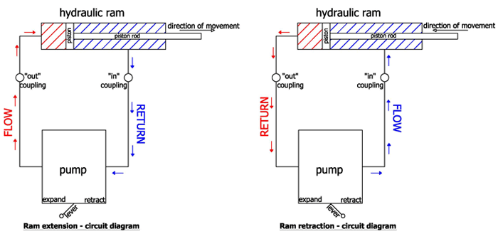
In order to pump out, or extend the length of the strut, hydraulic fluid is pumped into the full bore side of the piston (shown in red). This causes the piston to move from left to right as you look at the sketch above which in turn causes fluid to be displaced from the area behind the piston or annulus side (shown in blue) back into the pump reservoir, and since this is connected to the outer sleeve of the strut, causes the strut to increase in length. To get the strut to retract back in it is simply a case of reversing the flow on the pump. To (hopefully) simplify this, I have shown two schematic circuit diagrams below, one for extend and one for retract.

It is now obvious that to get this to work in practice, the operator must connect both hoses between the pump and the strut to complete the “circuit”. Only connecting a single hose will prevent this flow of fluid and will cause pressure to build up within the pump. A common call out fault for our operations guys.
Typical ratios between full bore and annulus areas is 2:1. This means that:
Twice as much fluid is required to expand the strut as is required to retract the same distance.
It is easy to cause the pump reservoir to overflow if retracting several struts fully.
Twice as much (push) force is generated whist expanding the strut as you can whist retracting (pulling) for the same pump pressures.
Consider for a minute that one of these struts is installed between 2 parallel walls that are not going to move very much. When the strut is pumped out to the point where it makes contact with both walls, there is no room for further expansion of the hydraulic unit. With the pump lever still in the “expand” position, the fluid continues to be pumped into the full bore area of the hydraulic ram although this time there is no increase in volume. This therefore causes the pressure in the strut to increase to a maximum pre-determined value which relates to the capacity of the pump. This is what we refer to as an “installation pressure” and is recommended to be kept in the region of 1000 psi (69 bar) for normal applications.
Once the desired length and/or pressure is achieved, the full bore pressure is isolated within the ram using the mechanical lock-off valve located within the “plumbing” on the strut. This enables the hoses to be de-pressurised and removed by hand without any loss of pressure.
Easy isn`t it! More on hydraulics next month.