The second Tyne Tunnel is a £260m scheme to alleviate traffic congestion through the existing single lane each way tunnel bore. It is one of the largest road infrastructure projects in the UK in recent years. The Tunnel, due for completion in 2011, is being constructed by French contractor Bouygues mainly using traditional cut-and-cover techniques on the North and South approaches and immersed precast concrete tunnel segments sunk into the river bed for the tunnel itself. Construction is complicated by the close proximity of the existing Tyne Tunnel which carries around 38,000 vehicles per day and consequently cannot be disrupted.
The Northern tunnel approach at Wallsend, as shown in the aerial photograph above right, is being constructed using a traditional cut-and-cover procedure and “bottom up” construction. The excavation is up to 20m deep adjacent to the river with 1m thick diaphragm walls extending to the rock bed 35m below.
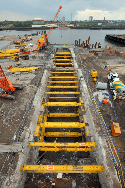 On the north side, the existing tunnel actually loops underneath the line of the new approach road with only a 2m height gap separating the two. A specialist top down construction technique is being used to construct the road in this area. It is within the cut and cover sections on the North side of the river where Groundforce’s vast array of proprietary hydraulic and mechanical struts are being employed. Here the trench for the tunnel approach is 12.5m wide and varies from 14m to 20m in depth. The depth of the excavations and the poor soils encountered on both sides of the river generate extremely high loads on the 1m thick diaphragm retaining walls.
An extremely stringent set of loading criteria was specified by the engineers for the temporary support system. In addition to the primary load due to ground pressure, additional load effects included; load due to a potential loss of prop situation arising, 50kN of applied accidental load and a potential 38ºC rise in ambient temperature.
MP500 (500 Tonne Prop)
Over 170 props in total have been supplied throughout the North cut and cover sections. To meet the design loadings, ranging from 2,800kN up to 10,000kN, a variety of both hydraulic and non-hydraulic props have been used including a specifically developed 5000kN capacity MP500 hydro-mechanical prop.
Fixed length non-hydraulic props were also designed to support the most heavily loaded areas and also the two transition chambers located immediately on each side of the river. These chambers will eventually be flooded to enable divers to break through into the submerged tunnel sections thus linking the tunnel under the river to the approach sections. The south transition structure is 30m deep and required individual prop loads of up to 1,400 tonnes, steel tubes up to 1m in diameter were needed to accommodate these large loads.
Although the concept of proprietary hydraulic propping was new to French contractor Bouygues, they were quick to appreciate that by utilising a proprietary solution, significant time savings on the build programme could be achieved with subsequent large cost savings. This concept has proved to be the case as excellent progress has been achieved on the North side.
Conclusions
The use of proprietary hydraulic struts for the temporary support of deep basement type constructions is on the increase. A large amount of research and technical data is available on these systems to provide a credible, practical, economic and sustainable alternative to traditional welded steel solutions.
Download PDF