Last month we looked at the basic theory behind calculating thermally induced load effects in steel props. This month we’re going to attempt to bring this more into Groundforce’s arena by applying these theories to one of our modular hydraulically operated props. We will set out to demonstrate that a hydraulic prop will be less susceptible to thermally induced loading than a traditional welded steel prop.
We’ll start with a quick recap of how Groundforce’s props work. The prop itself is made of a number of tubular steel extension sections bolted onto a telescopically adjustable hydraulic unit. The hydraulic ram itself is encased in a tubular steel sliding inner and outersleeve designed typically facilitate 1m of adjustment or hydraulic stroke. Diagrammatically they look like this:

Fig.1.
The prop is installed within an excavation by pumping it out typically between waling beams or concrete capping beams using a portable motorized pump. Fluid is forced into the full bore side of the ram (red) which displaces fluid from the annulus side (blue) with the nett effect of expanding the ram.

Fig.2.
Once pumped out and pressurised, a mechanical lock-off valve is closed to confine the fluid on the full bore side under pressure. Subsequent increases in load (including thermal effects) will naturally induce greater pressure within the ram and vice versa.
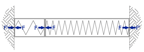
Back to the theory! If you consider the tubular steel components of a prop to behave like a very stiff spring under compressive loads, by introducing a hydraulic element (ram) to the prop, the confined column of load bearing fluid, shown red in the above diagrams, acts as a rather less stiff spring; despite the popular urban myth that fluid is incompressible. The diagram below shows this in a simplified form:

Fig.3.
We demonstrated in last month’s blog that the extra load in a confined steel strut due to thermal expansion is independent of prop length. Now if we add in a hydraulic ram, this will reduce the resultant overall stiffness of the prop; however, the extent to which this effect is felt depends on the proportion of hydraulic fluid to steel (the proportion of stiff to less stiff spring).
The rams in most Groundforce props have a one metre stroke. So a longer prop has a greater proportion of steel to fluid and the influence of the hydraulic unit is relatively smaller. There is also the added complication of considering how far the ram is pumped out and, therefore, how much fluid is actually in compression behind the piston head. Nevertheless, for a ram of a given cross sectional area, under given conditions, we can attempt to write equations for the thermal expansion and for the stress-strain properties of the hydraulic unit in a very similar way to Eq.1 to Eq.5 from May’s blog entry.
The only difference here is that we are dealing with a fluid so we need to consider volumetric strain (εv) rather than linear strain. This is expressed as change in volume over original volume, or:
Equation 6.

Below we have an equation analogous to Eq.2 from May’s blog. We have replaced Young’s modulus (E) with bulk modulus (K), and stress (σ) replaced by fluid pressure (P).
Equation 7.

Now pressure P = force (F) / full bore area (A) therefore Eq.7 can now be rearranged to give Eq.8 below:
Equation 8.

If we assume that the cross sectional area of the ram does not change during compression this can be re-written in terms of the length (as opposed to volume i.e.
Equation 9.

Expressed in words: the change in length in a hydraulic ram is equal to the applied force multiplied by the length of the column of fluid (in compression) divided by the cross sectional area of the ram multiplied by the bulk fluid modulus
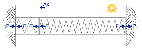
Returning now to our hydraulic prop in compression. By treating the hydraulic ram as a fixed column of fluid, which, once the lock off valve is engaged, it basically is. Let us also assume (as in figure 6) that the prop is fully restrained against axial extension (perhaps we are shoring some very stiff concrete piles with a large capping beam).

Fig.4.
Ignore for now the initial load in the prop due to earth pressures; the sun comes out (rare occurrence these days!) and starts to heat up the steel tubes. The tubes try to expand but find themselves restrained and therefore axial load starts to build up. As the steel element expands the hydraulic element will compress in response which will in turn reduce the expansion force in the steel element whilst increasing the pressure in the ram. A state of force equilibrium is eventually reached. This process is analogous to an expansion joint in a length of rail track.
We can express this equilibrium process graphically by substituting some numbers into the above equations as follows:
Firstly, considering the steel element. If we shall assume that the prop in question is a MP125 with 508 x 11 tubular steel extension pieces:
The C.S.A of the steel tube ≈ 9462 mm²
If a length of this tube is rigidly constrained and the temperature increases by 1°C ; the thermal force induced in the restraints is (using Eq.5,)
F = E α A δt
F = 210 x 12.6 x 10-6 x 9462 x 1
F = 25kN /°C
Now if the steel tube had been left to expand naturally, eq3 from last months blog can be rearranged as follows and used to predict the amount the tube will expand.
δL = α. δt. L
e.g. a 5m long tube will expand by 12.6 x 10-6 x 1 x 5 = 63 x 10-6 m
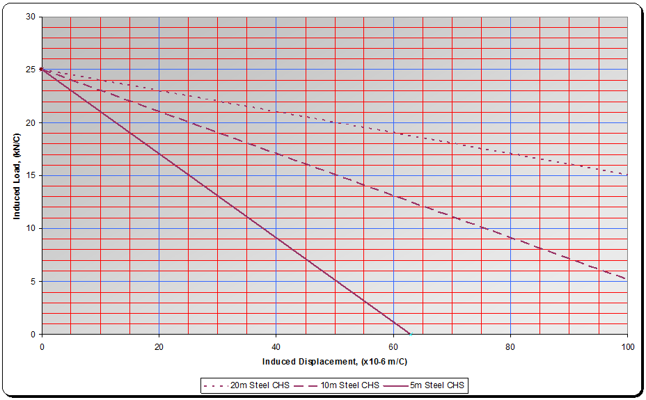
Load / expansion lines can be plotted on a graph for typical prop lengths in this case 5m, 10m & 20m as shown in graph 1 below:
Graph 1. – for 508 dia x 11.1mm CHS

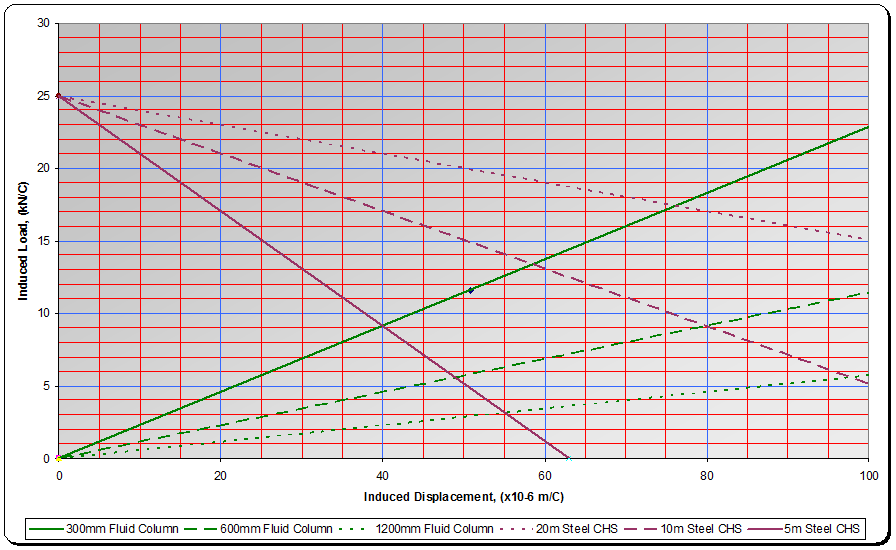
Turning now to the hydraulic ram, by plotting lines representing eq 9 onto the same graph, inclined lines can be drawn proportional to the length of the column of fluid in compression.
Three lines are drawn on graph 2 below representing 300mm 600mm and 900mm of hydraulic extension.
Graph 2.

The equilibrium point shown in Fig.5 below is achieved where the two lines for steel and fluid column intersect. This intersection is the true value of the induced load when taking into account the hydraulic unit.

Fig.5.
For example, a 10m long MP125 strut pumped out at ~half stroke (600mm) is subjected to a 10° increase in temperature. The load increase is determined by finding the intersection of the 10m strut line and 600mm ram line on graph 2 and multiplying the result by 10. i.e. the intersection point is corresponds to an increase on 9kN per °C i.e. 90kN for the 10° increase. Note this represents a reduction of ~55% from the potential load increase in a solid (non-hydraulic) tube. Note further that in the example above of a 10m long MP125, only 1.2mm of deflection is required to entirely absorb the thermal strain.
Summary
The hydraulic component clearly has a reducing effect on the thermally induced loading in a prop. In the example above using a MP125 prop, the reduction is equivalent effectively to halving the temperature effect.
An equally important influence on the thermal loading is the stiffness of the bearing structure and the surrounding ground. A relatively flexible sheet piled wall will provide less end restraint than say a secant piled wall / capping beam type construction. CIRIA C580 for example recommends reduction factors of 30% for stiff walls and 60% for flexible walls in stiff ground.
On the basis of the above, it would seem realistic to further reduce these factors when hydraulic struts are used, perhaps ignoring temperature effect altogether (in line with traditional practise in the UK) in the case of flexible sheet piled walls.
In the last blog in this trilogy will look at some case studies where we have actually measured the loads in props and also temperature variations to see if what happens in practice supports our theory.
Hope the weather improves by the time the next blog appears.