Returning this month to a more technical theme I have unashamedly plagiarised one of my colleague’s recent technical notes concerning the long serving (and suffering) trench crossing plate. These are one of the less glamorous pieces of kit in our hire fleet generally cut out of old ¾” thick boiler plate in 8’ x 4’ (apologies for the imperial units) size. To comply with current safety regulations they are generally coated with some sort of non-slip or anti-skid coating with a lifting hole burnt into each corner; and that is just about as sophisticated as they get.
Over the years I wish I had received a fiver for every time I had been asked “what load can these take” so here is the definitive answer.
1. Introduction
1.1. Basis of Design
A simplified load model has been applied that aims to satisfy the general conditions for safety required by the codes of practice (e.g. EN1991-2 and EN199302). Certain elements of this simplified model have been taken from EN1991-2, such as the spacing of patch loads to represent the force transmitted to the plate through a vehicle’s tyres.
Load model 1, from EN1991-2 shows a tandem drive axle loading, with a spacing of 2m in the width and 1.2m in the length and an area of the contact with the deck being a 0.4m by 0.4m square. As a simplification, the patch loads have been treated as point loads in this document.
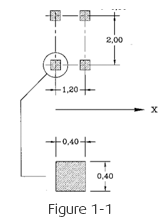
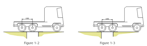
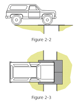
In most cases (since the spacing of axles is 1.2m) only one axle will ever be acting upon the roadplate at any given time. The worst case for bending failure of the plate would occur when this single axle is at the mid-span of the roadplate as shown in figure 1-2 below. In some cases, the span may be long enough that two axles act at the same time as shown in figure 1-3. This case would be less onerous in terms of bending but would give a more onerous case for shear.
1.2 Details of the Roadplate
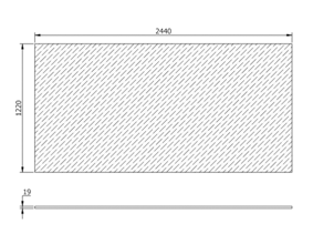
A standard roadplate is 1220mm x 2440mm and 19mm thick, steel grade is generally unknown but assumed to be equivalent to S275 grade for structural purposes. For verification, the road plate shall be modelled as an equivalent beam according to EN1993-1-7:2007 5.2.3.4.2 (1)
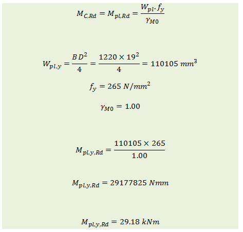
1.2.1 Resistance to Bending
For class 1 sections:
1.2.2 Resistance to Shear
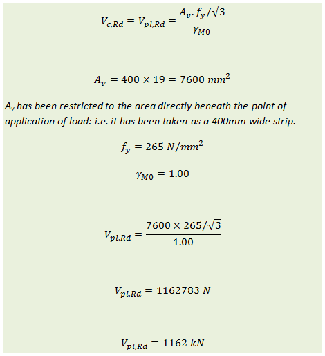
From the table derived in section 2 of this document, the maximum allowable load acting at the mid-span on a plate (limited by bending resistance) is 58.9 kN. If two axles of this weight were to act at once as in figure 1-3, this would lead to a worst case shear force of ±58.9 kN. Thus, it can be seen that the shear resistance is far in excess of any force that might reasonably be expected to act upon the roadplate. For the verification of safe loads on the roadplate, shear shall be ignored and only bending effects will be looked at in detail as this is the critical factor.
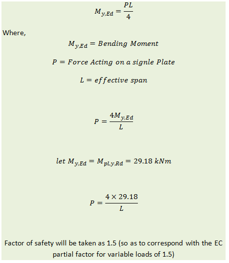
2. Allowable Loading on a Road Plate
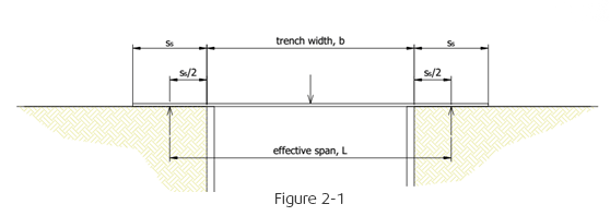
The load model outlined in figure 2-1 below, shows how the bending effect is calculated for varying widths of trench. The roadplate is treated as being simply supported with knife edge supports at the mid-width of the overlap to account for bedding material (shown in the diagram as Ss/2). Refer to DoT document “Traffic Advisory Leaflet 6/14” for further details on minimum bedding width. This document recommends that the minimum overlap Ss be 500mm.
In most cases, the vehicle that is crossing the roadplate will be too large to cross a single plate, and so multiple plates will be used side by side as shown in figure 2-3 below. In these cases, the load is spread across two adjacent plates and only a half-axle load is applied to each of the two plates.
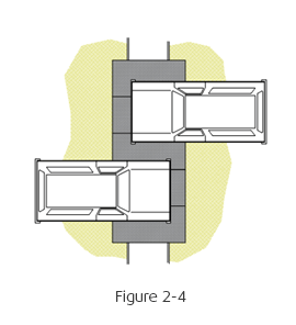
In some cases, it is possible that two half-axles will act upon the same plate at the same time as shown in figure 2-4 below. The potential for this scenario must be carefully considered when assessing the safe load upon the roadplates.
| Trench Width (m) |
Allowable Load on a Single Roadplate (kN) (FOS = 1.5) |
| 0.2 |
58.9 |
| 0.3 |
56.8 |
| 0.4 |
54.8 |
| 0.5 |
52.9 |
| 0.6 |
51.2 |
| 0.7 |
49.6 |
| 0.8 |
48.0 |
| 0.9 |
46.6 |
| 1.0 |
45.2 |
| 1.1 |
44.0 |
| 1.2 |
42.8 |
| 1.3 |
42.6 |
| 1.4 |
40.5 |
3. Other Important Factors that Must be Considered
3.1 Integrity and Bearing Capacity of bearing Ground
The ground must be assessed by the user/installer of the road plate to determine that the ground itself has sufficient strength to support the loads that will be acting upon it. This is especially important as, by its nature, a roadplate will be next to an opening, gap or excavation where the ground may be particularly sensitive to loading and prone to collapse.
3.2 Strength of Excvation Shoring
When using roadplates over a shored excavation, the additional load caused by the crossing traffic must be accounted for in the design of the shoring. Ensure that the shoring engineer is aware of the use of roadplates and that an additional surcharge has been added to the shoring design to account for traffic. If in doubt, ask!
3.3 Type of Mounting
Roadplates can either be surface mounted or recess mounted. The mounting is important in order to resist lateral loads, reduce noise generation and reduce discomfort for road users. Refer to Department for Transport document Traffic Advisory Leaflet 6/14 for a more detailed of selection of mounting.
3.4 Imposing a Weight Restriction and Consideration of Special Order Vehicles
In most cases, the 19mm roadplate will not be suitable for use on public highways for trenches over 700mm wide because at greater spans, the roadplate does not meet the strength requirements for normal highway loading (Refer to BD 21/01). The tables above show the maximum safe loads that can be applied. Special order vehicles and some heavier HGVs may exceed the loadings stated above.
Whether the roadplate is used on a highway or on a private access, it is important that a weight restriction corresponding with the safe loads in the table above are clearly in place during operation.
3.5 Speed Restriction
High speed impacts and braking forces can introduce lateral loading that can overcome the fixings/mounting that is holding the plate in place. Temporary speed restrictions, signage and other means should be used to limit the potential for excessive speed of traffic to damage or dislodge the roadplates. Refer to DoT document Traffic Advisory Leaflet 6/14 for more detailed information.
So there you have it, all you need to know about trench crossing plates. More next month; enjoy the lighter nights, it’s so nice to get home and be able see the garden again!